06/02/2024 01:55
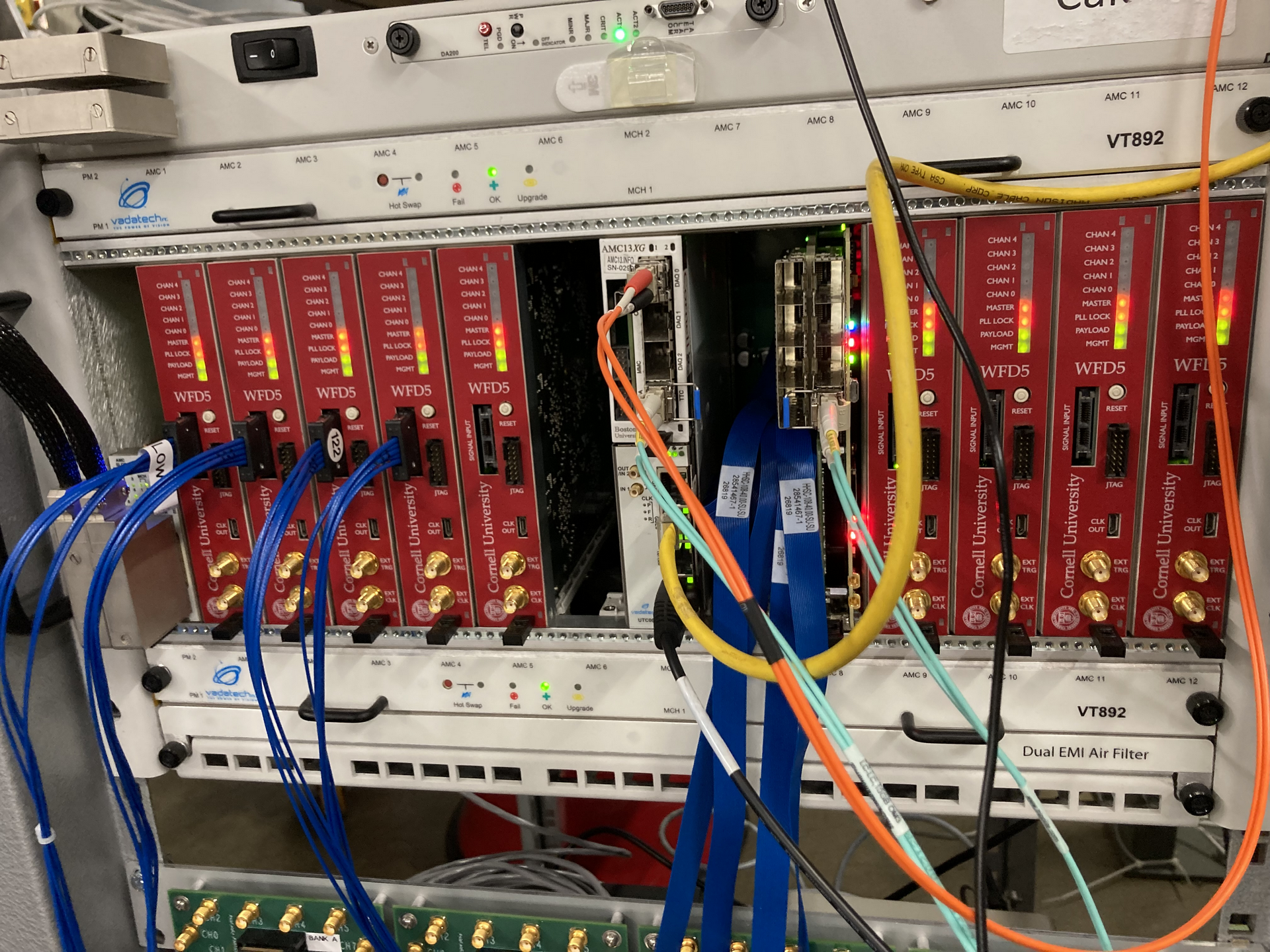
The full crate setup:
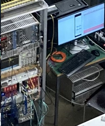
The best picture I have that includes the network box
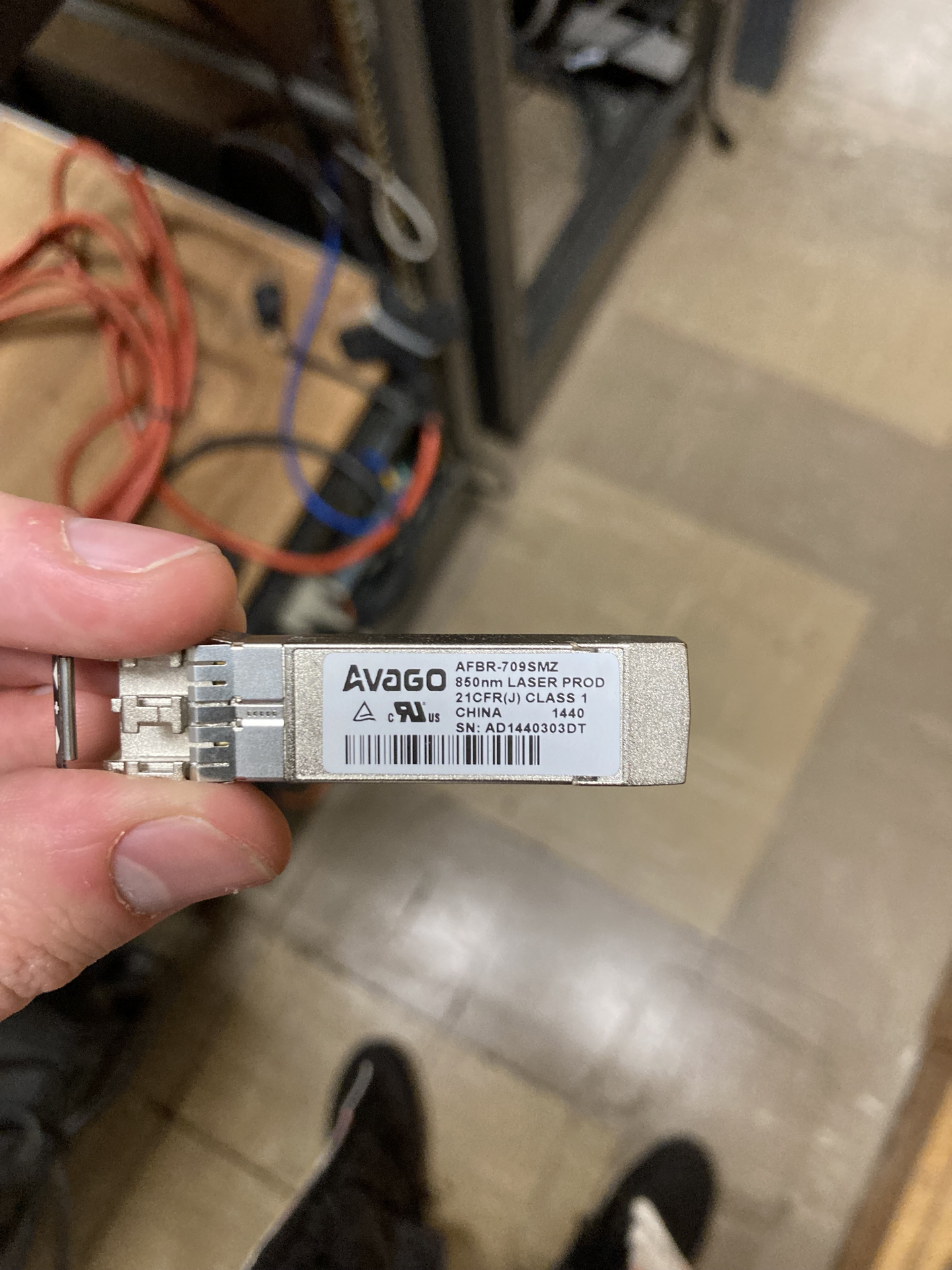
The SFP+ connector needed for AMC Module
Things we're missing:
- SFP+ Connector as pictured above
- An ethernet network splitter (though, I don't understand the point of this one)
- The blue ribbon connectors for the trigger boxes to FC7 trigger part of that card
06/02/2024 02:24
I'm lacking a vocabulary to describe this issues. But the piece that connects to the FC7 so that triggers can be read in is in two pieces. It's pretty obvious how to fit those two pieces together. But I cannot see for the life of me how they connect to the FC7.
07/02/2024 22:32
Tried installing XDMA driver (https://github.com/Xilinx/dma_ip_drivers/) on the newest machine running Linux Mint. This OS is not officially supported (as mentioned in the readme here: https://github.com/Xilinx/dma_ip_drivers/blob/master/XDMA/linux-kernel/readme.txt) and consequently(?) it fails to make.
07/02/2024 22:35
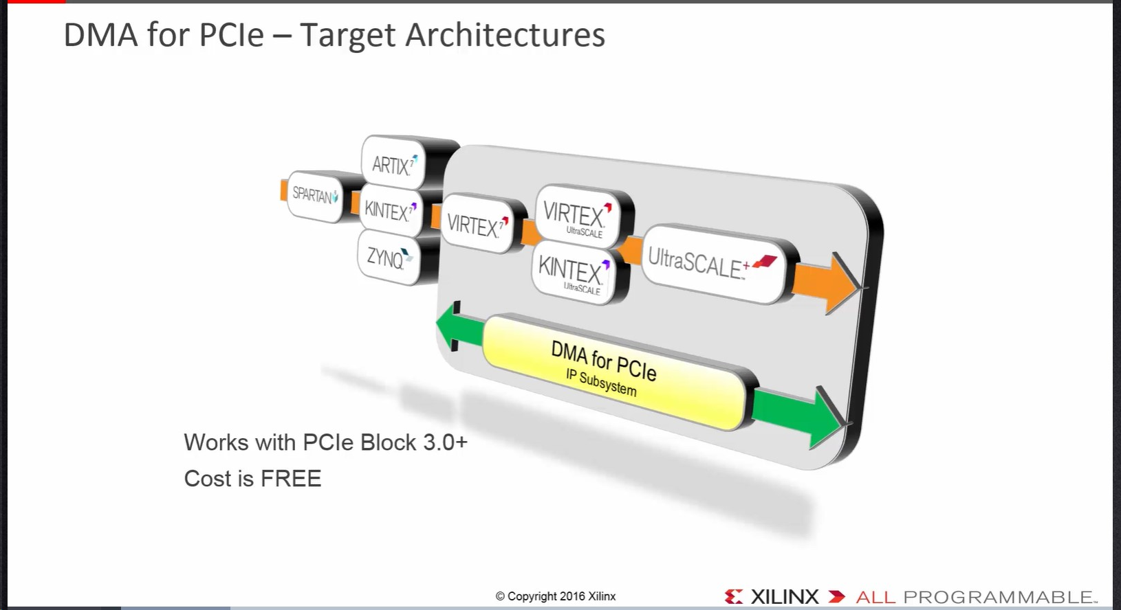
-- From https://www.xilinx.com/video/technology/dma-for-pci-express.html
It seems to imply that our board (kintex-7) isn't supported by DMA for PCIe.
The Kintex-7 is also not explicitly listed in supported FPGAs for the XDMA driver:
The PCIe DMA supports UltraScale+, UltraScale, Virtex-7 XT and 7 Series Gen2
devices.Please refer to the Xilinx documentation "PG195 DMA/Bridge Subsystem for PCI
Express" for details of the IP.
-- From https://github.com/Xilinx/dma_ip_drivers/blob/master/XDMA/linux-kernel/readme.txt
It is unclear whether Kintex-7 falls under "7-series" or not. In the PG195 product guide for the IP block, it is equally ambigious
Supports AMD UltraScale+™ , AMD UltraScale™ , AMD Virtex™ 7 XT Gen3 (Endpoint), and 7 series 2.1 (Endpoint) Integrated Blocks for PCIe. 7A15T and 7A25T are not supported
-- From https://docs.xilinx.com/r/en-US/pg195-pcie-dma/Introduction
However, it is clear that people (at numato and otherwise) have gotten DMA transfers to work using this IP block.
07/02/2024 22:49
Following the steps here:
https://github.com/Xilinx/dma_ip_drivers/blob/master/XDMA/linux-kernel/readme.txt
I was able to install the driver on the 'be' machine. I realized the last output message of a successful make install on 'be' was
‘xdma.ko’ -> ‘/lib/modules/3.10.0-1160.76.1.el7.x86_64/xdma/xdma.ko’
‘xdma.ko’ -> ‘/lib/modules/3.10.0-1160.76.1.el7.x86_64/xdma/xdma.ko’But the last two output messages of make install on 'fe01' were
‘xdma.ko’ -> ‘/lib/modules/3.10.0-1160.76.1.el7.x86_64/xdma/xdma.ko’
depmod: ERROR: fstat(4, nvidia-peermem.ko.xz): No such file or directory
‘xdma.ko’ -> ‘/lib/modules/3.10.0-1160.76.1.el7.x86_64/xdma/xdma.ko’
depmod: ERROR: fstat(4, nvidia-peermem.ko.xz): No such file or directory
This made me think this error message on 'fe01' has nothing to do with the actual xilinx driver installation. So I continued through the instructions of the readme and was able to ./load_driver.sh on both the 'fe01' and 'be' machines.
07/02/2024 23:37
In order to follow the Xilinx XDMA guide (https://www.xilinx.com/video/technology/dma-for-pci-express.html), I realized they do not load from flash memory, but rather directly upload a bitstream. So my plan is to program from my laptop while the device is in 'fe01' while 'fe01' is on. To do this, I need to see if
echo 1 > /sys/bus/pci/rescan
echo 1 > /sys/bus/pci/rescantruly works as a "reset" for the pcie bus to load a new FPGA bitstream (in this case from flash memory).
Following these steps I was able to reproduce the ability to communicate with the card over PCIe.
- Plug in the pcie card into 'fe01', turn it on. I don't see the card under lspci
- Load the bitstream into flash memory following the getting started nereid guide (https://numato.com/kb/getting-started-with-pci-express-on-nereid/)
- Following the suggestion of this comment on reddit (https://www.reddit.com/r/FPGA/comments/1993seu/comment/kicczq1/?utm_source=share&utm_medium=web2x&context=3) we boot the FPGA from configuration memory
echo 1 > /sys/bus/pci/rescan- Using the steps below, check ability to reproduce talking with card over pcie
18/01/2024 05:51
I realized I never looked to carefully at the board on fe01 when I used
lspci -vvafter programming. So I programmed the board using the .bin file generated on Vivado 2023.2 on the newest dektop, powered the desktop down, and swapped the card into fe01. Then, I looked again atlspci -vvand noticed:[root@fe01 pcimem]# lspci -vv | grep -A 34 "04:00.0"
04:00.0 Memory controller: Xilinx Corporation Device 7024
Subsystem: Xilinx Corporation Device 0007
Control: I/O+ Mem+ BusMaster+ SpecCycle- MemWINV- VGASnoop- ParErr- Stepping- SERR- FastB2B- DisINTx-
Status: Cap+ 66MHz- UDF- FastB2B- ParErr- DEVSEL=fast >TAbort- <TAbort-SERR- <PERR- INTx-
Latency: 0, Cache Line Size: 64 bytes
Interrupt: pin A routed to IRQ 11
Region 0: Memory at f5f80000 (32-bit, non-prefetchable) [size=512K]
Capabilities: [40] Power Management version 3
Flags: PMEClk- DSI- D1- D2- AuxCurrent=0mA PME(D0+,D1+,D2+,D3hot+,D3cold-)
Status: D0 NoSoftRst+ PME-Enable- DSel=0 DScale=0 PME-
Capabilities: [48] MSI: Enable- Count=1/1 Maskable- 64bit+
Address: 0000000000000000 Data: 0000
Capabilities: [60] Express (v2) Endpoint, MSI 00
DevCap: MaxPayload 512 bytes, PhantFunc 0, Latency L0s <64ns, L1 unlimited
ExtTag- AttnBtn- AttnInd- PwrInd- RBE+ FLReset- SlotPowerLimit 225.000W
DevCtl: Report errors: Correctable- Non-Fatal+ Fatal+ Unsupported-
RlxdOrd+ ExtTag- PhantFunc- AuxPwr- NoSnoop+
MaxPayload 256 bytes, MaxReadReq 512 bytes
DevSta: CorrErr- UncorrErr- FatalErr- UnsuppReq- AuxPwr- TransPend-
LnkCap: Port #0, Speed 5GT/s, Width x4, ASPM L0s, Exit Latency L0s unlimited, L1 unlimited
ClockPM- Surprise- LLActRep- BwNot- ASPMOptComp-
LnkCtl: ASPM Disabled; RCB 64 bytes Disabled- CommClk+
ExtSynch- ClockPM- AutWidDis- BWInt- AutBWInt-
LnkSta: Speed 5GT/s, Width x4, TrErr- Train- SlotClk+ DLActive- BWMgmt- ABWMgmt-
DevCap2: Completion Timeout: Range B, TimeoutDis-, LTR-, OBFF Not Supported
DevCtl2: Completion Timeout: 50us to 50ms, TimeoutDis-, LTR-, OBFF Disabled
LnkCtl2: Target Link Speed: 5GT/s, EnterCompliance- SpeedDis-
Transmit Margin: Normal Operating Range, EnterModifiedCompliance- ComplianceSOS-
Compliance De-emphasis: -6dB
LnkSta2: Current De-emphasis Level: -6dB, EqualizationComplete-, EqualizationPhase1-
EqualizationPhase2-, EqualizationPhase3-, LinkEqualizationRequest-
Capabilities: [100 v1] Device Serial Number 00-00-00-01-01-00-0a-3506:00.0 Ethernet controller: Broadcom Inc. and subsidiaries NetXtreme BCM5761 Gigabit Ethernet PCIe (rev 10)
Subsystem: Dell Device 026dIn particular,
Region 0: Memory at f5f80000 (32-bit, non-prefetchable) [size=512K]
no longer looks like:
Region 0: Memory at 51100000 (32-bit, non-prefetchable) [disabled] [size=512K]
I.e. it's not disabled. That means I should be able to communicate with it. So I used vivado's software to communicate (https://github.com/numato-viya/pcimem)And entered the command:
sudo ./pcimem /dev/mem 4126670848 w 0xffffff12
where 4126670848 is the decimal value of the hex code f5f80000. And we see we are sucessfully able to write and readback![root@fe01 pcimem]# sudo ./pcimem /dev/mem 4126670848 w 0xffffff12
/dev/mem opened.
Target offset is 0xf5f80000, page size is 4096
mmap(0, 4096, 0x3, 0x1, 3, 0xf5f80000)
PCI Memory mapped to address 0x7f1bd8988000.
Value at offset 0xF5F80000 (0x7f1bd8988000): 0x0
Written 0xFFFFFF12; readback 0xFFFFFF12
08/02/2024 00:12
An attempt at communicating with board's DDR3 memory following this guide:
https://www.xilinx.com/video/technology/dma-for-pci-express.html
I had make some edits, for one he's using a different board so I substitute my board in.
-
Create a new block design
-
Go to the board tab
-
Drag PCI Express from the list of IPs, click 4x lanes
-
Drag the DDR3 SRAM from the list of IPs
-
Run Block Automation. Change the h2c and c2h channels to 1 each.
-
Run Connection Automation for everything by hitting the top checkbox on the left
-
Click the "optomize routing" button just to clena up the display. My display looks like this when all this is done:
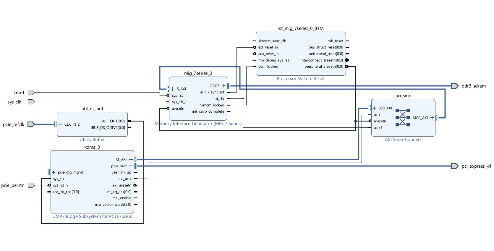
-
Now go to File->Save Block Design
-
Under the sources tab, right click the design and create and HDL Wrapper. Keep the bubble that lets vivado automatically handle it checked.
-
Then click generate bitstream. Allow it to run syntehsis and implementation first.
This fails to generate bitstream with this error:
[DRC NSTD-1] Unspecified I/O Standard: 1 out of 137 logical ports use I/O standard (IOSTANDARD) value 'DEFAULT', instead of a user assigned specific value. This may cause I/O contention or incompatibility with the board power or connectivity affecting performance, signal integrity or in extreme cases cause damage to the device or the components to which it is connected. To correct this violation, specify all I/O standards. This design will fail to generate a bitstream unless all logical ports have a user specified I/O standard value defined. To allow bitstream creation with unspecified I/O standard values (not recommended), use this command: set_property SEVERITY {Warning} [get_drc_checks NSTD-1]. NOTE: When using the Vivado Runs infrastructure (e.g. launch_runs Tcl command), add this command to a .tcl file and add that file as a pre-hook for write_bitstream step for the implementation run. Problem ports: sys_clk_i.I wlll try to see if I can resolve this by playing with the clock input
08/02/2024 01:15
Replaced the clock with the clcoking wizard instead (similar to how they do it in this guide https://numato.com/kb/vivado-design-suite-create-microblaze-based-design-using-ip-integrator-with-nereid-kintex-7-pci-express-development-board/). This allowed the bitstream to compile, but I was not able to get lspci to recognize the programmred board.
Furthermore, ./load_driver.sh still complained it could not find the board.